|
NEURONAL WIRING
1 Neuronal Connectivity I: by R. Durbin
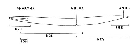
The neuronal connectivity data for C. elegans had been assembled by J. G. White, E. Southgate, J. N. Thomson, S. Brenner from 5 animals (N2T, JSH [L4 male], N2U [adult hermaphrodite], N2Y [adult male], JSE [L4 hermaphrodite]) and was later revisited by R. M. Durbin. For each neuron, the results originally obtained and published by White et al can be seen in MoW as:
1. connectivity diagrams (for nerve ring and RVG region synapses),
2. tables (for synapses in ventral cord).
[the total number of synapses for each neuron = synapses in the diagram + synapses listed in the table].
Results obtained by R. Durbin are reviewed in his thesis (Part I and Part II).
Also, revised and tabulated data for each neuron's connectivity in the nerve ring and RVG regions (from N2U and JSH animals) was provided by Durbin which can be seen as a text list (directions about this text list are provided below) as well as in Wormbase on individual neuron ("cell") pages [the total number of synapses for each neuron = synapses in the Durbin list or WB table + synapses listed in the MoW table].
It must be noted however, there is more extensive data available as handwritten notes/graphics from White et al group which are currently kept as part of the Wormatlas physical archive in AECOM.
The instructions below are reproduced from the neurodata readme file:
This directory contains a file: neurodata.txt which is a tab delimited Unix ASCII text file containing the synaptic connectivity data from two electron microscope reconstructions of the nerve ring, N2U and JSH.
These are data collected by John White, Eileen Southgate, Nichol Thomson and Sydney Brenner (White et al, Phil Trans Roy Soc B 314:1-340, 1986). The data in the file are not exactly those in the paper -- when they were entered various inconsistencies were found and corrected. Also the paper used data from other reconstructions in areas outside the ring and RVG, which are not represented here.
The columns in the file are:
<neuron 1>
<neuron 2>
<synapse type> see below
<reconstruction> one of JSH, N2U
<number of synapses>
The synapse type is one of
Gap_junction direction is not visible here
Send unambiguous chemical synapse from neuron 1 to neuron 2
Send_joint chemical synapse from 1 where 2 is a possible or
shared recipient
Receive unambiguous chemical synapse 2 to 1
Receive_joint chemical synapse from 2 where 1 is a possible or
shared recipient
See the paper for discussion of the joint type synapses (they may be called "multiple" there).
I think N2U was a hermaphrodite adult and JSH an L4 male*, but do not rely on the differences being sex or stage specific: there is likely to be equally as much random difference between animals; you will be able to see there are significant differences between bilaterally symmetric sides.
Richard Durbin 980225
*WormAtlas editors' note: While Richard Durbin suggests that JSH was an L4 male, it is now believed that this animal was an L4 hermaphrodite.
2 Neuronal Connectivity II: by L.R. Varshney, B.L. Chen, E. Paniagua, D.H. Hall and D.B. Chklovskii
(Also see Neuronal network of C. elegans: from Anatomy to Behavior (Doctoral Dissertation Thesis) by Beth Chen, 2007 (pdf file))
This data was first discussed by Chen, Hall, and Chklovskii, in "Wiring optimization can relate neuronal structrure and function", PNAS, March 21, 2006 103: 4723-4728 (doi:10.1073/pnas.0506806103). More recently, full analysis of the data can be found by Varshney, Chen, Paniaqua, Hall and Chklovskii in "Structural properties of the C. elegans neuronal network" PLoS Comput. Biol. Feb 3, 2011 3:7:e1001066 (doi:10.1371/journal.pcbi.1001066). Any publication made utilizing the following data should make a reference to this paper. Correspondence should be addressed to bethlchen at yahoo.com or mitya at janelia.hhmi.org.
2.1 Connectivity Data
Connectivity Data-download (pdf-large file!)
Connectivity Data-download (excel file)
Provided is a compilation of an updated version of C. elegans wiring diagram (280 nonpharyngeal neurons (CANL/R were excluded since they have no obvious synapses), covering 6393 chemical synapses, 890 electrical junctions, and 1410 neuromuscular junctions). Pivotal works published by White et al, 1986 and Hall and Russell, 1991 had provided neuronal circuitry in the head and tail, but lacked connection details for 58 motor neurons in the ventral cord of the worm. Most of the missing data for this region is now compiled by using original electron micrographs (EM) and handwritten notes from White and co-workers. The dorsal side of the worm around the mid-body was not previously documented. Using original thin sections prepared by White et al, 1986, new EM images were generated and neuron processes of animal “N2U” in this region were reconstructed. The new version of the wiring diagram incorporates original data from White et al, 1986, new reconstructions, as well as updates based upon later work (Hobert and Hall, 1999; and Durbin, R. M., 1986, Achacoso and Yamamoto W.S., 1991, Chen. Inconsistencies within the data were reconciled by checking against original EM and handwritten notes from White and co-workers. Over 3000 connections, including chemical synapses, electrical junctions, and neuromuscular junctions were added and/or updated from the previous version. Due to rather sparse sampling of data along lengths of the sub-lateral, canal-associated lateral, and mid-body dorsal cords, connectivity ambiguities for a select few neurons remain.
The current wiring diagram is considered self-consistent under the following criteria: (I) A record of Neuron A sending a chemical synapse to Neuron B must be paired with a record of Neuron B receiving a chemical synapse from Neuron A. (II) A record of electrical junction between Neuron C and Neuron D must be paired with a separate record of electrical junction between Neuron D and Neuron C. From our compilation of wiring data, including new reconstructions of ventral cord motor neurons, we applied the above criteria to isolate records with mismatched reciprocal records. The discrepancies were reconciled by checking against electron micrographs and White and coworkers’ lab notebooks. Connections in the posterior region of the animal were also cross-referenced with reconstructions published by Hall and Russell, 1991. Reconciliation involved 561 synapses for 108 neurons (49% chemical “sends”, 31% chemical “receives”, and 20% electrical junctions).
The included file is the updated wiring diagram (as of 2/2/2006) listing the number of connections by neuron, its synaptic partner, and by type of synapses (incoming chemical synapse or “receives”, outgoing chemical synapse or “sends”, electrical junction and neuromuscular junction (NMJ)). Please refer to White et al, 1986 for neuron naming conventions. Neuromuscular junctions in this file derive from actual reconstructions and do not include extrapolations (see Neuron Connectivity to Sensory Organs and Muscles below). Please see NeuronFixedPoints below for identity of muscles involved in NMJ connections. Labels are as follows:
N1: Neuron 1 name
N2: Neuron 2 name
Type: Type of synapse: S: Send or output (Neuron 1 pre-synaptic to Neuron 2); Sp: Send-poly (Neuron 1 is pre-synaptic to more than one postsynaptic partner. Neuron 2 is just one of these post-synaptic neurons, see Figure 1 below. In White et al, 1986, these polyadic synaptic connections were denoted by “m” in the tables of Appendix 1); R: Receive or input (Neuron 1 is post-synaptic to Neuron 2); Rp: Receive-poly (Neuron 1 is one of several post-synaptic partners of Neuron 2. See Figure 1 and above); EJ: Electric junction; NMJ: Neuromuscular junction (only reconstructed NMJ's are represented).
It must be noted that at polyadic synaptic sites, not all “send-poly” were faithfully labeled as such in White et al, 1986. Some pre-synaptic connections were labeled simply as “sends”. Reconciliation of chemical synapses did not previously distinguish between send from send-poly and receive from receive-poly. In this new reconciliation, the total number of send and send-poly is equal to the total number of receive and receive-poly (S+Sp=R+Rp). Every documented synapse is now listed in this Table, both with respect to the sending neuron and with respect to the receiving neuron(s).
Nbr: Number of synapses between the given neuron pair.
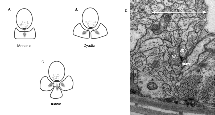 Fig 1: Polyadic synapses are those where more than one postsynaptic partner receive input at one release site. Postsynaptic partners can include other neurons, muscle arms (muArm) and rarely hypodermis (synapses onto hypodermis are not included in this dataset analysis). A. A synapse with one postsynaptic partner. B,C. Polyadic synapse types. D. A dyadic synaptic site. In C. elegans, synapses are identified by dark pre-synaptic tufts at the region of vesicle release. No specialization is generally visible for post-synaptic elements. In this electron micrograph, the pre-synaptic neuron VA4 appears directed towards both VD4 and a muscle arm. This type of synapse is labeled as send-poly (Sp) and receive-poly (Rp) in the connectivity data.
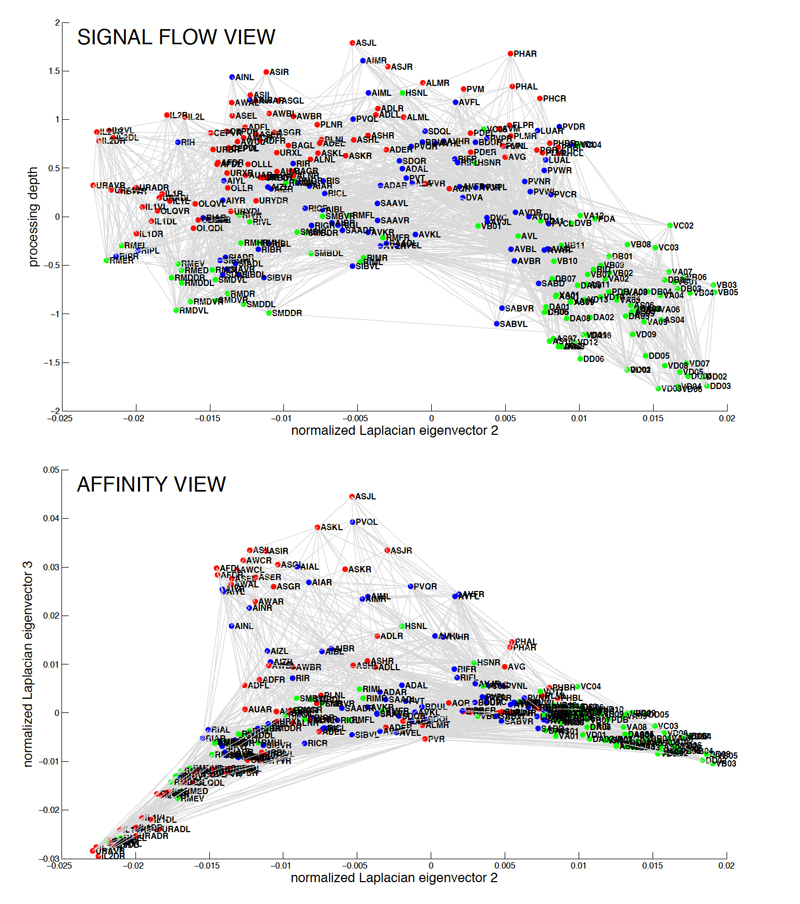
Fig 2: The C. elegans wiring diagram is a network of identifiable, labeled neurons connected by chemical and electrical
synapses. Red, sensory neurons; blue, interneurons; green, motorneurons. Signal flow view shows neurons arranged so that
the direction of signal flow is mostly downward. Affinity view shows structure in the horizontal plane reflecting weighted
non-directional adjacency of neurons in the network. Clicking on figure opens a PDF version.
2.2 Neuron Description (Neuron Types)
Neuron type-download (pdf)
Neuron type-download (excel)
This file contains neuron position, synapse position, and various neuron morphology designations that can be used for further analyses. Neuron position is defined by the center of the cell body projected onto the AP axis of the worm. These positions are determined from various diagrams of neuronal cell bodies in the adult worm and presented in this atlas. By dividing the worm's AP axis into three parts, head, mid-body and tail, we designate head neurons as neurons with cell bodies located at <25% along the AP axis from the anterior end of the worm, mid-body neurons with cell bodies lying between 25% and 75% of the axis, and tail neurons located at >75%.
In this file, we also note any applicable ambiguities and gaps in the wiring diagram. Due to technical constraints, wiring data in the posterior region of the worm was obtained from serial sections of 2 animals, 1 hermaphrodite (JSE) and 1 male (N2Y) (White et al, 1986). The difficulty in tracing neural processes across different animals contributed much of the ambiguity in this region. In the region posterior to the vulva, the scarcity of high power EM's on the dorsal side affects the reconstruction of 39 neurons. Neurons AS11, DA9, DB7, VD11-13, RID, PDA, PDB have partial dorsal data whereas AS7-10, DA7-8, DB5-6, DD4-6, VD7-10 completely lack dorsal reconstructions. All neurons with processes in the sublateral nerves have incomplete reconstructions. Unlike the ventral and dorsal cords, the sublateral cords were never examined under high power magnification and, therefore, never fully reconstructed. Despite the near completion of the wiring diagram, which maps connections between neurons, there is a lack of data specifying the location of individual synapses in the worm. For this project, synapse positions were approximated into 3 gross categories: head (< 25% along AP axis from the nose), mid-body (between 25% and 75%), and tail (>75%). Connections denoted in diagrams showing the nerve ring and anterior ventral cord in White et al, 1986 are designated to be in the head. Connections derived from the reconstruction of animal JSE (see Figure 2) are designated to be in the tail. Data in this posterior region was also cross referenced with Hall and Russell, 1991. The remaining connections are assumed to be located in the mid-body. This data set of synapse positions was created by looking at individual neurons by themselves. Positions of synapses across pairs of neurons are not reconciled into these gross categories. Thus a synapse is considered to be in proximity of the cell body if both neurons fall within the same defined areas of head, mid-body, or tail. Labels are as follows:
Neuron: Name of neuron
Soma Position: Position of cell body along the AP axis of worm body. 0=tip of nose; 1=tail tip.
Soma region: Cell body position by head, mid-body, or tail region.
Span: Length of neuron span. Neurons spanning <25% of worm body (e.g., motor neurons in the ventral cord, neurons with processes confined to the nerve ring and neurons confined in the mid-body) are defined to have short spans (S). All other neurons are defined to have long spans (L).
Ambiguity: If applicable, code for the type of ambiguity. Codes beginning with M denote ambiguity citedin White et al, 1986. Codes beginning with R denote ambiguity found in reconstructions during update of wiring diagram (MB=cell body position ambiguous, MTS=tail synapses ambiguous and/or sparse connections in the tail; MAS=anterior body ambiguous and/or sparse connections in the anterior; MD=dorsal side ambiguous; MAD=anterior and dorsal side ambiguous; MS=neurons with sublateral processes not covered by reconstructions. RDI=dorsal reconstruction incomplete; RDM=dorsal reconstruction completely missing; RVI=ventral reconstruction incomplete.)
TotHead: Total number of synapses in the head including EJ and NMJ.
TotTail: Total number of synapses in the tail including EJ and NMJ.
TotMid: Total number of synapses in the mid-body including EJ and NMJ.
S_Head: Number of “sends” or output synapses in the head, includes send polyadic synapses (see Figure 1) and NMJ.
R_Head: Number of “receives” or input synapses (includes polyadic synapses) in the head.
S_Mid: Number of “sends” or output synapses in the mid-body, includes polyadic synapses and NMJ.
R_Mid: Number of “receives” or input synapses (includes polyadic synapses) in the mid-body.
S_Tail: Number of “sends” or output synapses in the tail, includes polyadic synapses and NMJ.
R_Tail: Number of “receives” or input synapses (includes polyadic synapses) in the tail.
AY NeuronType: Letter codes denoting ganglion group as defined by Achacoso and Yamamoto W.S., 1991, where A=anterior ganglion, B=dorsal ganglion, C=lateral ganglion, D=ventral ganglion, E=retrovesicular ganglion, F=posterolateral ganglion, G=ventral cord neuron group, H=pre-anal ganglion, J=dorsorectal ganglion, K=lumbar ganglion.
AYNbr: Numeric identifier given by AY for each neuron.
Note: Sum of S_Head and R_Head does not include electrical junctions (EJ), therefore, does not equal TotHead. Similar is true for mid-body and tail.
 2.3 Neuron Connections to Sensory Organs and Body Muscles
Neuronfixedpoints-download (pdf)
Neuronfixedpoints-download (excel file)
In our model, 200 sensory and motor neurons are wired to 20 sensory features (2 amphids, 6 inner labial sensilla, 6 outer labial sensilla, 2 deirid sensilla, 2 postdeirid sensilla, 2 phasmids), 95 body wall muscles, and one representative muscle for the vulva and anus, respectively. The identity of sensory neurons and the locations of their corresponding sensory organs are based on diagrams of amphids, phasmids, and putative touch sensors from this atlas. A neuron is assumed to make a single connection to a given sensory organ.
The position of each muscle is defined as the midpoint between anterior and posterior extremities of the sarcomere region (White et al, 1986, Dixon and Roy, 2005), projected onto the AP axis; see example in Figure 3. Neuron-to-muscle connections for the first 32 muscles in the head are detailed by White et al, 1986. For the remaining muscles, direct neuron-to-muscle mapping is not available. In this case, we assume that motor neurons connect to muscles where positions of neuromuscular junctions overlap the sarcomere region of a given muscle. Dixon and Roy, 2005 have shown that muscle arms from muscle cells in the mid-body do not appear to reach beyond the sarcomere region of each cell. Since more than one muscle can overlap the NMJ region of a single neuron, we approximate the number of connections to each muscle by taking the total number of NMJ's made by a given neuron, divided by the number of muscles overlapping the NMJ region. For neurons lacking complete reconstruction, especially ones on the dorsal side of the worm, the number of neuron-to-muscle connections is assumed to be the average NMJ per muscle from fully reconstructed neurons of the same class. The last three body muscles in tail of the worm do not overlap with NMJ regions. The connections to these muscles are assigned to the posterior-most motor neurons in the ventral and dorsal cords. Labels are as follows:
Neuron: Neuron name
Landmark: Description of structure to which a neuron is connected (Sensory=sensory organ; SensoryNB=sensory organ with neurite currently unclassified as axon or dendrite (such as AVM); MANAL=anal muscle, MVULVA=vulva muscle; MDR/L#=dorsal body wall muscle on right/left side, numbered from anterior to posterior; MVR/L#=ventral body wall muscle on right/left side numbered from anterior to posterior.
Landmark Position: position of structure (along A-P axis) to which a neuron must extend to be connected. For sensors that span the length of the worm, such as ALM and PLM, position is represented by the midpoint of neuron’s sensory process. A single point located at the vulva represents the vulva muscles. A single point located at the anus represents the enteric muscles.
Weight: Number of connections to the landmark (NMJ’s have been extrapolated for neurons with incomplete reconstruction, see above) .
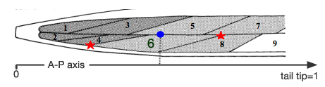
Fig 3: Schematic of the anterior-most body muscles (head muscles) in the dorsal left quadrant. Red stars mark the anterior and posterior extremities of the sarcomere region of muscle cell #6. The position of the cell is defined as the midpoint of these two points projected onto the AP axis, represented here by the blue circle.
2.4 Lineage Analysis
Lineage_Part1-download (pdf-very large file!)
Lineage_Part1-download (excel file)
Lineage_Part2-download (pdf-very large file!)
Lineage_Part2-download (excel file)
We constructed a matrix of "relatedness" between neurons expressed in terms of distances using published embryonic and post-embryonic lineage trees (Sulston and Horvitz, 1977; Sulston et al, 1983). “Relatedness” between two neurons is found by first identifying the last common progenitor cell. Then, for each cell, we count the number of cell divisions from the common ancestor where each division is defined as a single unit in length. The lineage distance is the total number of cell divisions leading to the two neurons with the initial division from the common progenitor counted only once. 279 non-pharyngeal neurons are included in the analysis (Along with CANL/R, VC6 was omitted since it only makes one NMJ). Post-embryonic blast cells are mapped back to the embryonic lineage such that all cells can be traced to the anterior daughter of the fertilized egg P0. In cases where variability has been noted in the left-right pair of post-embryonic cells, we assigned the precursors to what is most often observed in experiment (Sulston and Horvitz, 1977). Specifically, blast cell P1 is assigned to the right and P2 is assigned to the left. Cells that appear to be random in left/right division have been arbitrarily assigned such that P3, P5, P7, P9 are right and P4, P6, P8, P10 are left. AVFR has been assumed to come from P1.aaa and AVFL from W.aaa. Ambiguities of post-embryonic P cells affect mostly ventral cord motor neurons.
Labels are as follows (due to length of the file, lineage data has been separated into 2 files; Lineage_Part1.csv and Lineage_Part2.csv);
Neuron 1: Neuron 1 name
Neuron 2: Neuron 2 name
Relatedness: Number of cell divisions separating Neuron 1 and Neuron 2 as described above.
3 Neuronal Connectivity III: by K. Oshio, Y. Iwasaki, S. Morita, Y. Osana, S. Gomi, E. Akiyama, K. Omata, K. Oka and K. Kawamura
Database of Synaptic Connectivity of C. elegans for Computation
4 C. elegans Neural Network: by N. Bhatla
An Interactive Visualization of the C. elegans Neural Network
Features:
- Click on neurons to re-center them and see what other neurons they're connected to.
- Specify a start neuron and an end neuron to find the shortest path between 2 neurons (e.g. BAG [putative carbon dioxide sensor] and HSN [egg-laying motor neuron]).
- Zoom in and out to view neurons more than just 1-degree away.
- View all connections in the visible portion of the network (makes a dense spiderweb) by checking the "Show more connections on the graph" checkbox.
- View and search the network of individual neurons. By default, neuron groups (e.g. pairs of neurons) are displayed, but this is an oversimplification, and the individual neuron network is a more accurate representation of the true network.
Cells included:
- 302 individual neurons in 118 groups
- 7 pharyngeal muscles
- 2 pharyngeal marginal cells
- 2 pharyngeal gland cells
- 1 pharyngeal basement membrane
- 1 muscle class
5 Neuronal Wiring (Hermaphrodite): Extrapolated Connectivity from Motoneuronal Iterativity by G. Haspel and M. J. O'Donovan
Haspel and O’Donovan 2011-download (pdf)
Haspel and O’Donovan 2012-download (pdf)
CeConnMtrcs_170626.mat-download (.mat file)
In the previously published connectivity data (specifically, White et al, 1986, Chen et al. 2006 and Varshney et al. 2011) the connectivity of motoneurons in the posterior half of the animal was missing or partial as this portion of the nervous system was not reconstructed. When the connectivity data for motoneurons in the anterior half was analyzed according to motoneuronal function, repeating patterns were detected which were defined as iterativity (Haspel and O’Donovan 2011). The iterativity of each class of motoneuron was analyzed and it was statistically validated that this iterativity was higher than expected by chance. The iteration could then be extrapolated into the posterior portion to complete a model of motoneuronal connectivity (Haspel and O’Donovan 2011, Haspel and O’Donovan 2012).
The model includes six functional segments, each composed of 11 motoneurons of 7 classes, and 6 pairs of body wall muscle. In Haspel and O’Donovan 2012, each segment included two DA motoneurons and an updated model includes only one per segment. The reason for the change is that while in the nematode, there are nine DA motoneurons, the posterior two (DA08 and DA09) are distinct morphologically and in some expression patterns, and possibly in function.
The Matlab file included here (CeConnMtrcs_170626.mat) includes six matrices:
- A_conn_full/seg are connectivity matrices for chemical synaptic connections (directed and weighted according to MoW). Seg is for a "functional segment" made of 11 motoneurons and six pairs of muscle cells. Full is for the complete model made of six interconnected segments. Columns are presynaptic (evident from connections to muscle cells in rows 12-17).
- J_conn_full/seg are the same for electrical junctions (undirected and weighted) for a segment and full model
- Names_conn_full/seg give the names of motoneurons and muscle cell pairs in "A_..." and "J_..."
Correspondence should be addressed to haspel@njit.edu
6 Male Wiring
The C. elegans Male Connectome: the Set of All Synaptic Interactions in the Nervous System
See also Wormwiring for connectome of both sexes: The Nematode Connectomics
The complete neural connectome for the adult male tail has been derived from electron microscopy of serial thin sections (Jarrell et al., 2012). This subsystem of the male neuroanatomy contains 170 neurons (81 male-specific and 89 shared neurons with the hermaphrodite) and 64 muscles. Analysis of the synaptic patterns, including the relative “weights” of synapses between neuron pairs, allows the male mating behavior to be modeled on the basis of known connectivity between neurons, sex muscles and the gonad.
The thin section data used in this paper came from animal N2Y, first studied at the MRC (see Sulston et al., 1980 and White et al., 1986). Current information on each neuron in the male tail is available on the WormWiring website. This website includes a new 2D viewer of neuron shape; “Neuron Trace”, as well as a “Partner Tree” viewer that shows relative strengths of connectivity from any neuron which is based on the relative sizes of synapses (for either male or hermaphrodite wiring). The annotated images of animal N2Y are accessible from WormImage.
Supplementary materials associated with the Jarrell et al. paper, including 29 pages of text, figures, references and a movie, can be reached from:
http://www.sciencemag.org/content/337/6093/437/suppl/DC1.
Extensive additional supporting online materials (Databases S1 to S9) for the Jarrell paper are available from: http://worms.aecom.yu.edu/jarrelletalSOM.html.
An ongoing project in the Emmons lab is also aiming to derive a connectome for the adult male nerve ring from serial sections; see WormWiring and the Emmons Lab website.
An editorial about the male tail connectome is written by Chklovskii and Bargmann, 2012.

|